
How Does High Temperature Affect CNC-Machined Plastic Tolerances?
A deep engineering look into thermal drift, coefficient of thermal expansion (CTE), and process strategies for holding precision tolerances in performance polymers.
Introduction
In modern manufacturing, transitioning structural components from aluminum, brass, or stainless steel to engineering polymers offers immense advantages: substantial weight reduction, natural self-lubrication, chemical resistance, and dielectric properties. However, when engineers specify metal-like tolerances on plastic parts, they inevitably collide with a fundamental physical property: polymer sensitivity to thermal fluctuations.
Unlike metals, which possess rigid crystalline lattices with relatively low coefficients of thermal expansion (CTE), polymers consist of entangled macromolecular chains. When exposed to heat—whether generated during high-speed CNC milling or encountered in ambient service environments—these chains flex, expand, and shift significantly. At PlasticCNCPro, our machining facility in Dongguan encounters this challenge daily. Our goal is to assist mechanical designers, sourcing managers, and R&D teams in anticipating thermal drift and configuring machining workflows that reliably maintain dimensional stability.
Plastics expand anywhere from 3 to 10 times more than common metals across the same temperature gradient. Maintaining repeatable micron-level tolerances requires controlling both cutting heat and operating environmental equilibrium.
The Science of Thermal Expansion in Plastics
CTE Comparison: Plastics vs. Metals
The Coefficient of Thermal Expansion (CTE) expresses the fractional change in length per degree of temperature change. For precision components, CTE determines how quickly a bore shrinks or an outer profile expands as heat enters the part. The disparity between metals and standard engineering polymers is stark:
| Material | Material Family | Linear CTE (10⁻⁶ m/m/°C) | Dimensional Sensitivity |
|---|---|---|---|
| 304 Stainless Steel | Ferrous Metal | 16 – 18 | Very Low |
| Aluminum 6061-T6 | Non-Ferrous Metal | 23 – 24 | Low |
| PEEK (Unfilled) | High-Performance Polymer | 45 – 50 | Moderate |
| POM-C (Acetal / Delrin) | Engineering Thermoplastic | 80 – 110 | High |
| Nylon 6/6 (PA66) | Polyamide | 80 – 90 | High (Hygral & Thermal) |
| UHMW-PE | Polyolefin | 150 – 200 | Extremely High |
| PTFE (Teflon) | Fluoropolymer | 120 – 160 | Extremely High |
Dimensional Drift
Consider a 100 mm POM-C (Acetal) guide block machined in a climate-controlled shop at 20°C. If this part is deployed into an industrial enclosure where the operational temperature reaches 50°C (ΔT = 30°C), its linear expansion is:
ΔL = 100 mm × (100 × 10⁻⁶ /°C) × 30°C = 0.300 mm (0.0118 in)
An expansion of 0.30 mm will instantly violate any drawing calling for a ±0.05 mm tolerance. The part was entirely in-spec on our coordinate measuring machine (CMM) at 20°C, yet it fails in the customer's machine because ambient thermal growth exceeded the permissible tolerance window.
Glass Transition Temperature (Tg)
The glass transition temperature (Tg) marks the reversible transition in amorphous polymers (and the amorphous phase of semi-crystalline polymers) from a hard, glassy state to a rubbery, compliant state. Beyond Tg, the rate of thermal expansion jumps abruptly, and stiffness drops dramatically. If a machined part operates near its Tg, mechanical loads will quickly cause creep, warping, and permanent tolerance loss.
Thermal Challenges During the Machining Process
Friction-Induced Heat
Unlike aluminum or steel, polymers are poor thermal conductors. When a carbide cutting edge shears through plastic, the heat generated by mechanical friction cannot conduct swiftly into the stock or the tool. Instead, it concentrates directly at the shear zone and chip boundary.
If the chip is not evacuated immediately, this localized heat softens the material, creating a gummy cut edge, microscopic smeared burrs, and deep internal hoop stresses that remain trapped in the workpiece.
Thermal Distortion as a Silent Variable
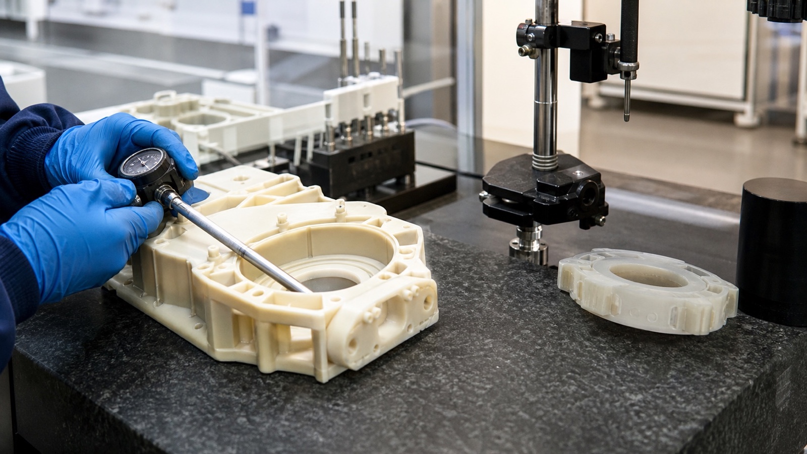
Thermal distortion often presents as a silent defect. A machinist measures a bore while the part is still warm on the vacuum table or vice, confirms it meets a ±0.02 mm bore callout, and unclamps it. As the component cools down to room temperature over the next four hours, the polymer contracts inward. The bore shrinks undersized, while flat faces potato-chip due to asymmetric stress relief.
Material-Specific Sensitivities
Every polymer responds distinctively to cutting heat. Understanding these behavioral boundaries helps us match the right cutting regime to each grade:
High-Stability Polymers (PEEK, PEI, PPS)
Possess high heat deflection temperatures (HDT) and relatively moderate CTEs. Unfilled PEEK withstands moderate cutting friction well, while glass-fiber reinforced PEEK (e.g., PEEK-GF30) drops CTE down near aluminum levels, granting remarkable dimensional hold under heat.
Semi-Crystalline Polymers (POM / Acetal, PET)
POM is popular for high lubricity and excellent machinability, but exhibits high CTE (90–110 × 10⁻⁶/°C). Asymmetrical material removal quickly induces internal stress relief, requiring balanced roughing cuts on opposing sides to avoid curved profiles.
Hygroscopic & Soft Polymers (Nylon PA6/PA66, UHMW-PE)
Nylon combines thermal expansion with moisture absorption swelling. UHMW-PE has an exceptionally high CTE and low melting threshold, requiring sharp, polished razor tooling and aggressive chip evacuation to prevent melting and elastic deformation.
Fluoropolymers (PTFE, PVDF)
PTFE exhibits a crystalline phase transition around 19°C that accompanies a 1% volume shift, making micro-tolerances below 20°C virtually impossible without stringent room temperature management and dedicated creep compensations.
Design and Process Strategies for Thermal Stability
At PlasticCNCPro, we rely on a multi-stage approach to mitigate thermal effects. From raw stock conditioning to final coordinate metrology, our shop enforces specific measures across four critical disciplines:
The Role of Annealing
Extruded or compression-molded plastic stock enters the machine shop with substantial molded-in stresses. When stock is cut away, those locked stresses release unevenly. For demanding geometries, we implement a stepped thermal cycle:
Optimizing Machining Parameters
The fundamental rule when machining polymers is: cut the plastic, do not rub it. High spindle speeds combined with too low a feed rate result in cutter rubbing, which instantly builds friction heat. Machinists must maintain a high chip load so that the thermal energy created by shear deformation is carried away inside the exiting chip rather than sinking into the parent stock. We use single-flute and polished two-flute solid carbide end mills with generous positive rake angles and sharp cutting margins.
Cooling and Lubrication
Directing cold compressed air (such as via vortex tubes) to the cutting interface removes chips instantly and cools the tool edge without liquid contamination. When wet coolant is required for heat transfer, water-soluble, non-reactive cutting fluids must be selected. Solvents or standard petroleum-based cutting oils can cause severe environmental stress cracking (ESC) in amorphous materials like PC, PMMA, and PSU.
Fixturing Techniques
Excessive clamping pressure creates elastic deformation that rebounds into geometric errors when unchucked. Moreover, if a part is clamped rigidly in a vise and expands under cutting heat, it buckles upward. We utilize vacuum chucks, custom-contoured soft jaws, and torque-limiting fixtures that secure parts firmly while accommodating minute lateral thermal motion without introducing flexure.
Best Practices for Tolerancing Plastic Parts
Designing for Thermal Mismatch in Assemblies
When plastic bushings, liners, or housings pair with metal shafts or cast frames, differential expansion must be engineered into nominal clearances:
The "Less is More" Philosophy
Tolerancing plastic parts using standard ISO 2768-m or metal-machining defaults (±0.02 mm / ±0.001 in) across non-critical dimensions multiplies manufacturing cost, increases inspection disputes, and adds zero functional value. Restrict tight tolerance bands strictly to critical bearing interfaces, seal glands, or dowel pin locations. Allow generous boundaries (±0.1 mm to ±0.2 mm) on non-mating features.
Accounting for Environmental Factors
Always indicate the reference measurement temperature on your drawing (standard metrology baseline is 20°C / 68°F). If your component operates inside an oven, aerospace sensor housing, or subsea manifold at a vastly different temperature, communicate that service window to our engineering team. We can calibrate CNC dimensions so that the part lands perfectly within spec at its point of use.
Frequently Asked Questions (FAQ)
What temperature is too hot for plastic?
"Too hot" depends directly on the polymer structure. Standard commodity polymers like HDPE or PVC lose structural rigidity above 60°C to 70°C. Engineering polymers such as POM and Nylon withstand continuous use up to 90°C–105°C, while high-performance polymers like PEEK, PEI (Ultem), and PAI (Torlon) endure continuous operating temperatures between 170°C and 250°C. Exceeding a polymer's Continuous Service Temperature or Glass Transition (Tg) causes rapid yield strength decay, creep, and irreversible dimensional loss.
What is the typical tolerance for CNC machining plastics?
For standard commercial plastic CNC machining, typical achievable tolerances range from ±0.075 mm to ±0.125 mm (±0.003 in to ±0.005 in). With climate-controlled machining, stabilized annealed stock, and rigid polymers like PEEK or Acetal, precision tolerances of ±0.025 mm (±0.001 in) can be held on specific features. Softer polymers like UHMW-PE or PTFE typically require wider tolerance allowances (±0.15 mm or greater).
Is .005 a tight tolerance for plastic?
A ±0.005 inch (±0.127 mm) tolerance is a comfortable, standard production tolerance for small to medium-sized parts (under 100 mm / 4 inches) in rigid polymers like POM, PEEK, PC, or ABS. However, if the feature spans 300 mm (12 inches) or is machined from high-expansion materials like unfilled PTFE or UHMW-PE, holding ±0.005 inches across wide seasonal temperature swings becomes very challenging without climate-controlled deployment.
At what temperature does plastic start to deform?
Plastic begins to expand immediately upon any temperature increase, governed by its linear CTE. However, permanent physical deformation under load occurs at its Heat Deflection Temperature (HDT), which is typically measured at 0.45 MPa or 1.8 MPa load. For instance, POM-C displays an HDT of roughly 110°C at 1.8 MPa, whereas unfilled PEEK reaches 152°C, and 30% glass-filled PEEK pushes deformation resistance above 300°C.
Conclusion & Next Steps
Controlling thermal behavior is the defining factor in precision plastic CNC machining. Because polymers expand rapidly, conduct heat poorly, and carry residual processing stresses, achieving tight tolerances demands specialized manufacturing techniques: balanced cutting feeds, sharp positive-rake tooling, multi-stage stress relief annealing, and temperature-stabilized metrology.
Early collaboration between mechanical design engineers and CNC machinists eliminates costly redesigns. At PlasticCNCPro, we review your 2D drawings, 3D CAD models, target operating environments, and mating parts before a single cut is made, ensuring that the material selection and tolerance scheme fit your real-world application.
Have a Tight-Tolerance Plastic Project?
Upload your drawings for engineering feedback and a manufacturability review.
Connect with Our Plastic Machining Specialists
Send us your 2D drawings, 3D CAD files (STEP/IGES), material specifications, and tolerance requirements. Our engineering team at PlasticCNCPro will review your project and provide comprehensive quotation support within 24 hours.