
Custom Plastic Support Brackets
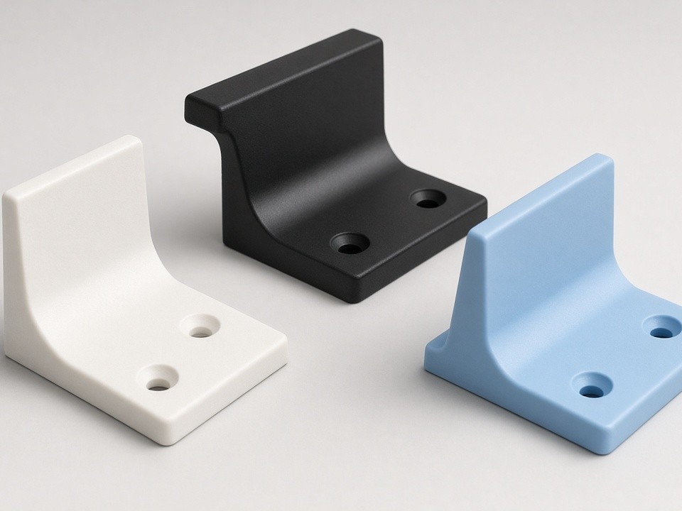
Plastic support brackets serve as load-bearing or alignment components in machinery where metal parts would introduce unwanted conductivity, corrosion, or weight. They appear commonly in conveyor frames, enclosure mounts, valve assemblies, and sensor fixtures.
- Linear Tolerance
- ±0.05 mm
- Tight Datum Control
- ±0.02 mm
- Quote Turnaround
- 2 Days
Material Selection for Bracket Performance
Material choice depends on mechanical loads, chemical exposure, and temperature range. The right grade balances stiffness, impact resistance, and dimensional stability for the operating environment.
POM
Good stiffness and low moisture uptake for general positioning tasks.
Nylon 6 / 66
Chosen where impact resistance and vibration damping matter.
UHMW-PE
Suited to wear strips and sliding guides.
PEEK / PPS / PVDF
Maintain dimensional stability under higher temperatures and aggressive media.
Reinforced Grades
Glass or carbon fiber reinforcement increases rigidity when brackets must span longer distances without deflection.
CNC Processes Applied to Bracket Production
Most plastic support brackets begin as milled blanks on 3-axis or 5-axis centers. Operations are sequenced to hold geometry and reduce setups.
Discuss Your Geometry-
01
Face & Pocket Milling
Face milling for mounting surfaces and pocket milling for weight reduction.
-
02
Drilling & Tapping
Precise fastener holes, with threaded inserts installed post-machining for repeated assembly cycles.
-
03
Turning
Applied when the bracket incorporates cylindrical bosses or shoulders.
-
04
Slotting & Contour Milling
Creates mounting tabs and clearance features.
Tolerances and Surface Requirements
Standard production holds tight control on mounting features, with tighter options available for optical or pneumatic alignment.
Critical Holes
±0.05 mm
Overall Length
±0.1 mm
Datum Surfaces
±0.02 mm
Flatness / 100 mm
0.05 mm
Surface finishes range from 1.6 µm Ra as-machined to 0.8 µm Ra after light sanding or vapor polishing on visible faces.
Matching Process to Part Geometry
Bracket shape drives the most efficient machine setup. Selecting the right process minimizes setups and protects thin features.
| Bracket Geometry | Recommended Process |
|---|---|
| Simple L-shaped or U-shaped with through holes | Vertical mill from plate stock |
| Undercuts or angled mounting faces | 5-axis positioning to reduce setups |
| Turned diameters plus milled features | Two operations on a mill-turn center |
| Thin webs or tall ribs | Higher-modulus grades to avoid distortion during machining or in service |
Typical Project Profiles
-
Buyers order plastic support brackets when an existing metal design needs weight reduction or electrical isolation.
-
Low-volume runs of 10–200 pieces often follow a prototype stage where the part is validated on the machine before committing to tooling.
-
Replacement brackets for older equipment frequently require reverse engineering from samples.
-
OEMs in semiconductor handling, packaging lines, and laboratory automation regularly source brackets with integrated cable guides or sensor pockets that cannot be molded economically at their volumes.
Inspection and Documentation
First-Article Inspection
Each batch receives CMM or height-gauge verification of critical dimensions.
Compliance Documents
Material certificates and RoHS or REACH statements supplied on request.
Export Packaging
Foam inserts or custom dividers prevent surface damage during transit.
Request a Quotation
Send your 2D drawing or 3D model, material preference, annual quantity, and any special requirements such as color, markings, or cleanliness standards. Our team reviews the files and returns a fixed quotation with lead time within two working days.
- info@plasticcncpro.com
- Quotation Turnaround
- Fixed price with lead time within 2 working days