
Material Selection Guide · Fluoropolymers
PTFE vs. ECTFE: Which Fluoropolymer Is Better for Machined Parts?
PTFE and ECTFE are two of the most requested fluoropolymers in our CNC shop — and two of the most commonly confused. This is the exact comparison we walk through with customers before a single chip is cut, so you can lock in the right material for your machined parts with confidence.
Introduction: The Engineering Dilemma of Fluoropolymers
Fluoropolymers exist for the jobs other plastics refuse to do: lining vessels that hold concentrated acids, sealing pump housings that see hot aggressive media, insulating assemblies that must stay inert and dimensionally stable for years. In chemical processing plants, semiconductor fabs, medical laboratories and industrial automation, they are often the last material standing when solvents, halogens and heat combine.
Within that family, two names dominate our quotation requests: PTFE (Polytetrafluoroethylene) and ECTFE (Ethylene Chlorotrifluoroethylene). On a datasheet they look like cousins — both are fluorine-rich, chemically tough and readily machined. On the CNC, however, they behave very differently, and a part that performs beautifully in one material can quietly fail in the other. Specify PTFE for a load-bearing chemical enclosure and it will creep; specify ECTFE for a 200 °C seal and it will soften long before PTFE even breaks a sweat.
The goal of this article is simple: to give you a clear decision-making framework based on what your part will actually experience — chemistry, temperature, mechanical load, permeation risk and tolerance demands — rather than on brand familiarity. Everything below comes straight from our workbench experience machining both materials for global B2B customers.
Key takeaway
In the PTFE vs ECTFE decision there is no universally “better” material — only the right match between the polymer and the environment, load and tolerance your part will actually see.
At a Glance: Quick Comparison Table
If you only have sixty seconds before a design review, this is the summary we sketch on the whiteboard. Values are typical for unfilled grades at room temperature — real performance always depends on the specific grade, filler and stock shape.
| Property | PTFE (Teflon) | ECTFE (Halar) | Quick Verdict |
|---|---|---|---|
| Chemical resistance | Near-universal inertness — among the most chemically resistant plastics available. | Excellent across most acids, bases and halogens, with standout performance on wet chlorine and oxidizers. | PTFE |
| Temperature limit | Approx. 260 °C continuous service. | Approx. 150 °C continuous service. | PTFE |
| Mechanical strength | Soft, low hardness; creeps under sustained load. | Roughly double the tensile strength, noticeably higher hardness and stiffness. | ECTFE |
| Machinability (tolerance holding) | Cuts easily but keeps moving after the cut; tight tolerances are hard work. | More rigid, more stable dimensions, easier to finish to size. | ECTFE |
| Permeation resistance | Good, but small molecules migrate through faster than in ECTFE. | Among the best of all fluoropolymers. | ECTFE |
| Typical cost | Generally lower resin cost with the widest stock-shape availability. | Higher resin cost; fewer stocked sizes, so raw material may need special ordering. | PTFE |
Verdicts reflect the most common outcome for machined components — your application may weight these factors differently. Always confirm final properties against the specific datasheet.
Understanding the Materials
Both materials belong to the fluoropolymer family, but they are built from different chemistry and processed in fundamentally different ways. That single fact explains nearly every practical difference you will encounter downstream — from how the part behaves in service to how it behaves on the milling machine.
What is PTFE (Teflon)?
PTFE is a fully fluorinated carbon chain — every hydrogen atom on the backbone replaced by fluorine. That structure is why it is famously slippery, non-stick and almost totally inert to chemical attack. For decades it has been the gold standard for applications where nothing else survives: hot, wet, aggressive, high-purity — PTFE is usually the default answer engineers reach for first.
In the hand, PTFE feels soft and distinctly wax-like. You can dent a block with a thumbnail, and it slides across a bench almost by itself. Those qualities make it a superb seal and bearing face — and a genuinely difficult precision-machining material. It also cannot be melt-processed: PTFE stock shapes are compression-sintered from powder, which is why the material carries internal stresses that matter later in the machining story. Grades range from virgin PTFE to glass-, carbon- and bronze-filled compounds that improve wear and creep behavior.
What is ECTFE (Halar)?
ECTFE is a copolymer of ethylene and chlorotrifluoroethylene, with alternating units along the chain that produce a tougher, semi-crystalline thermoplastic. Unlike PTFE, it is melt-processable — extruded and molded stock shapes are dimensionally uniform, and finished parts can be welded, which opens up fabrication options PTFE simply does not offer.
In practical terms, ECTFE keeps most of the chemical muscle fluoropolymers are chosen for, while adding roughly twice the tensile strength of PTFE, higher hardness, far better impact resistance and notably stronger permeation resistance. It is best known under the Halar trade name and is widely specified for linings, ducts and wetted components in the most demanding chemical environments.
Side-by-side profile
PTFE · Polytetrafluoroethylene
The inert, heat-proof specialist
Continuous service around 260 °C, near-universal chemical inertness and the lowest friction of any solid polymer. The trade-off: it is soft, creeps under load, is difficult to bond, and moves after machining.
ECTFE · Ethylene Chlorotrifluoroethylene
The tough, weldable workhorse
A melt-processable fluoropolymer with roughly twice PTFE’s tensile strength, higher hardness, top-tier permeation resistance and easy weldability — in exchange for an approximate 150 °C practical ceiling.
Critical Differences for Machined Components
Three differences decide the PTFE vs ECTFE question in the majority of the projects we quote: how the material carries load, how far its chemical and thermal envelope stretches, and how well it blocks fluids from passing through the wall of the part.
Mechanical Strength and Durability
ECTFE is the clear mechanical winner. With roughly double PTFE’s tensile strength, a much higher hardness and a stiffer modulus, it is the right choice wherever a machined part needs structural integrity: housings, brackets, valve components, guides and any detail that takes impact or carries bolt load. It holds its shape because its molecular structure simply resists deformation better.
PTFE, by contrast, is famous for a failure mode we see constantly: cold flow (creep). Under sustained load — even at room temperature — virgin PTFE slowly deforms and squeezes out of the loaded zone. The classic example is a gasket or valve seat torqued down properly at installation, only to relax over weeks until clamping load is lost and the joint leaks. For precision machined parts, creep means dimensional instability, and dimensional instability means a part that passes final inspection but fails in the field.
Why it matters
If your drawing calls for tolerances tighter than a few hundredths of a millimeter and the part carries load, virgin PTFE will fight you at every step — it keeps moving long after it leaves the machine. Either switch to ECTFE, specify a filled PTFE grade, or design the part so load is carried by another component.
Chemical and Thermal Resistance
Both materials are outstanding chemically — this is the fluoropolymer family, after all. But PTFE is in a category of its own: it is essentially inert to nearly everything industry throws at it, resisting attack from virtually all acids, bases and solvents, and it remains serviceable at approximately 260 °C continuous. When the question is “what survives everything, including heat?”, the answer is almost always PTFE.
ECTFE covers a broad chemical range too, and in specific niches it is not just adequate — it is exceptional. It excels with strong mineral acids, wet chlorine, chlorine dioxide, sodium hypochlorite and hot concentrated sulfuric acid, environments that destroy most engineering plastics. Its limitation is thermal: with a continuous service temperature of around 150 °C, it is roughly a hundred degrees short of PTFE. Above that ceiling, the decision makes itself.
Field note
For chlorine, hypochlorite and oxidizing-acid containment parts, we routinely steer customers to ECTFE. The combination of chemical resistance, permeation performance and weldability beats PTFE for these specific applications — and the machined parts hold their dimensions better in service.
Permeation Resistance
Permeation is the slow migration of molecules directly through a material’s wall — no cracks, no holes, just diffusion at the molecular level. For linings, duct components and containment hardware, it is the silent failure mode: the vessel looks perfect while traces of aggressive media slowly pass through to attack the structure behind it.
This is where ECTFE earns its reputation. Its denser, semi-crystalline structure gives it some of the lowest permeability of any fluoroplastic, which is why it is frequently preferred for lining and containment parts where preventing fluid migration is vital — chemical delivery systems, wet-process ducting and chlorine-handling hardware among them. PTFE is good, but its structure lets small molecules pass through faster; where a barrier must stay tight for years, simply thickening a PTFE lining often just buys time, whereas ECTFE provides a genuine barrier.
Machining Guide: How PTFE and ECTFE Behave on the CNC
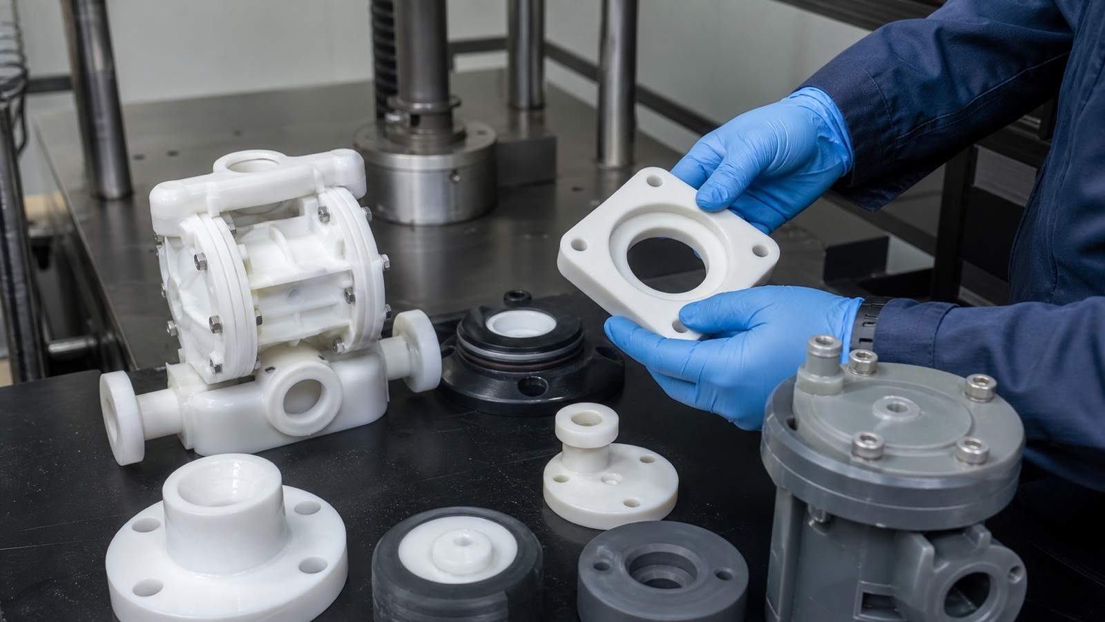
On paper, both materials are “easy to machine” — they are soft, and virgin grades contain nothing that dulls an insert. In reality, they are gummy, thermally insulating and prone to movement. Customers come to us precisely because these behaviors make fluoropolymer machining unforgiving for general-purpose shops. Here is how we manage each factor.
Tooling Requirements
The rule for both materials is the same: razor-sharp, highly polished cutting edges. Freshly ground uncoated carbide or high-speed steel tools with generous positive rake angles shear the material cleanly; any dullness or rough edge causes the tool to rub instead of cut, which tears the surface, leaves a fuzzy finish and generates heat. We re-sharpen or swap tools aggressively on these jobs — an edge that would run all day in aluminum is already past its best on a PTFE seal face.
Geometry matters as much as sharpness. High rake and polished flutes help chips evacuate instead of smearing into the cut, and light finishing passes with a dedicated clean tool give the surface quality that O-ring grooves, seal faces and sliding surfaces demand.
Heat Management
PTFE and ECTFE are both thermal insulators with very low thermal conductivity. Heat generated at the cutting edge has nowhere to go — it cannot drain into the part the way it does with metals — so it accumulates exactly where you do not want it. The results range from gummed-up edges and melted smears on ECTFE to glazed, stress-laden surfaces on PTFE, plus residual stresses that warp the part later.
Our approach: continuous coolant or a focused air blast on the cut zone, moderate spindle speeds, light depths of cut and zero dwell time with the tool rubbing. ECTFE adds its own consideration — mind its lower softening point, because aggressive dry cutting will locally melt the surface before you see smoke or discoloration.
Watch out
Aggressive dry cutting is the most common cause of rejected fluoropolymer parts we see. Heat at the edge melts the material, glazes the surface and locks in distortion that only appears days after machining — long after the part has shipped.
Tolerances
ECTFE’s rigidity is a genuine advantage at the inspection bench: it machines predictably and holds tighter tolerances with confidence. PTFE is another story. It is soft and springy under the tool, and because sintered stock shapes carry internal stresses, the material relaxes and moves after cutting — a bore that measures perfect on the machine can be out of position by the next morning.
Holding size on PTFE is a process, not a single setup. This is the sequence we use for tight-tolerance PTFE parts:
-
1
Stress-relieve the blank
Thermally anneal before final machining so sintered-in stresses release in the oven, not in your finished part.
-
2
Rough machine generously
Remove most of the stock early and leave finishing allowance on all faces rather than cutting to size in one pass.
-
3
Let it settle
Rest the part at stable room temperature so the material finishes moving before the critical dimensions are cut.
-
4
Finish light and sharp
Small depths of cut with freshly polished tooling and minimal clamping force keep the final geometry true.
-
5
Inspect late
Verify dimensions hours after the last cut, once the part has stopped moving — never straight off the machine.
Workholding
Both materials have a low modulus of elasticity, which means they distort under clamping pressure — and whatever distortion you clamp in, you machine in. Squeeze a PTFE block in a standard hard vise and it becomes a slightly barrel-shaped block; cut a flat pocket into it, release the vise, and the pocket is no longer flat.
Our fixes are simple but non-negotiable: soft jaws or fixture pads with large contact area, deliberate low clamping torque, full support under thin sections, and finishing of thin or delicate features last. For thin-walled parts we move clamping entirely off the part — vacuum fixtures or adhesive/tack mounting hold the work flat without point pressure. ECTFE is more forgiving than PTFE here, but neither material rewards a heavy hand.
When to Choose Which? A Decision Matrix
When customers ask us to settle the PTFE vs ECTFE question, we reduce it to their three or four dominant requirements. These are the two recommendation blocks we use internally:
Choose PTFE when…
-
Extreme temperature or friction is the driver — parts near 200–260 °C service, or seals and slides where the lowest coefficient of friction is the entire point.
-
Absolute chemical inertness is required in a non-structural role — gaskets, insulators and low-load bushings in media that would destroy every alternative.
-
Nothing may stick to the surface — release details, anti-fouling faces and non-stick wear surfaces.
Choose ECTFE when…
-
The part must survive physical abuse — housings, brackets and valve components that carry load, take impact or must not creep under bolt load.
-
Containment must be permeation-tight — linings, ducts and wetted hardware where even trace migration through the wall is unacceptable.
-
The part must be welded or bonded — ECTFE is melt-processable and joins far more readily than PTFE, which resists both welding and adhesion.
| Typical Machined Part | Our Usual Default | Why |
|---|---|---|
| Valve seats, soft seals, gaskets | PTFE (often filled) | Inertness, temperature capability and low friction; glass or carbon fillers control creep under bolt load. |
| Tank linings, duct components, wetted containment | ECTFE | Permeation barrier, impact toughness and the ability to weld the assembly. |
| Low-friction wear pads and insulators | PTFE | The lowest coefficient of friction of any solid polymer, in low-load applications. |
| Chemically exposed housings and brackets | ECTFE | The stiffness and impact resistance PTFE structurally cannot offer. |
Frequently Asked Questions (FAQ)
These are the questions we hear most often on quotation calls about fluoropolymer machined parts.
What are the key differences between PTFE and ECTFE?
The core trade-off is mechanical versus chemical-thermal. PTFE is the chemistry and temperature champion — near-universal inertness and service up to about 260 °C — but it is soft and creeps under load. ECTFE is the mechanical champion — roughly twice the tensile strength, higher hardness, far better permeation resistance and easy weldability — with still-excellent (though not universal) chemical resistance and a practical ceiling around 150 °C. Rule of thumb: inert or hot but unloaded, choose PTFE; loaded, impact-exposed or barrier-critical, choose ECTFE.
Is fluoropolymer the same as PTFE?
No. “Fluoropolymer” is the family of plastics built on fluorine chemistry — PTFE, FEP, PFA, PVDF, ETFE, ECTFE and others. PTFE is the oldest and best-known member, which is why the terms get used interchangeably. When a drawing or supplier says “fluoropolymer part,” always pin down the exact resin, because the machining behavior and performance envelope differ significantly across the family.
What are the disadvantages of PTFE?
Three main ones from a machined-parts perspective. First, cold flow: under sustained load PTFE deforms over time, which destroys dimensional stability in precision components. Second, softness: it scratches, dents and is difficult to hold in fixtures and to tolerance. Third, joining: PTFE is notoriously difficult to bond without special surface treatment and cannot be melt-welded at all. Filled grades mitigate some of these issues, at added cost and with changes to chemical-facing behavior.
Is ETFE better than PTFE?
Different, not better. ETFE trades some of PTFE’s chemical universality and non-stick character for much higher toughness and stiffness, making it attractive where mechanical abuse dominates — structural chemical-handling parts, protective films and linings. Compared with ECTFE, ETFE offers somewhat higher mechanical performance, while ECTFE generally wins on chemical resistance and permeation. If strength is the driver and temperatures are moderate, ETFE and ECTFE both beat PTFE; if inertness or heat dominates, PTFE remains the reference. It is worth comparing all three before locking a drawing.
Conclusion: Optimizing Your Material Selection
There is no better material in the abstract — only the right material for your part’s specific environment. PTFE is the answer when extreme temperature, lowest friction or absolute chemical inertness define success. ECTFE is the answer when the part must carry load, resist impact, block permeation or be welded and machined to stable dimensions. Most of the rework we are asked to rescue comes from choosing on familiarity rather than on the application environment — a decision that costs one prototype round to get right and several to get wrong.
Our strongest recommendation: settle the material before you finalize the CAD model. Tolerances, wall thicknesses, clamping features and joining details all change depending on whether the part is PTFE or ECTFE. Talk to your material supplier or machining partner early — a short engineering conversation before design freeze routinely saves weeks of iteration. We at PlasticCNCPro machine both materials (plus PVDF, PEEK, PPS, PEI and the wider engineering-polymer range) and regularly help customers re-select materials when heat, chemical exposure or dimensional-stability issues appear in existing designs.
Get a quotation
Discuss Your PTFE or ECTFE Machining Project
Send us your 2D drawing, 3D model, target material, quantity, tolerance and application details. Our engineers will review manufacturability, confirm the right fluoropolymer — or suggest a better alternative — and come back with a clear quotation and production recommendation. Prototypes, low-volume runs and repeat production are all welcome.